
DIRECTIONS FOR USE AND CALIBRATION OF THE SHARP EDGE TESTER
MODEL SET - 50
The following requirement or one similar to it appears in most U.S. Standards.
"An edge, projection, or corner of an enclosure, opening, frame, handle or the like, shall be smooth and rounded and not sufficiently sharp to cause a cut type injury when contacted during normal use or user maintenance."
The SHARP EDGE TESTER MODEL
SET - 50 was designed and developed to provide an objective means for judging the sharpness on an edge. Consistent results may be obtained with a minimum of experience if the following procedure is carefully followed.
1. INSTALLATION OF THE TAPE CAP
The TC-3 tape cap assembly meets all the latest U.L. standards incorporating three (3) layers of tape:
Bottom layer - 1/16 thk. Black foam Center layer - 1/32 thk. White foam
Top layer - 3 mil Tefion tape
Plus - the addition of a center guide line
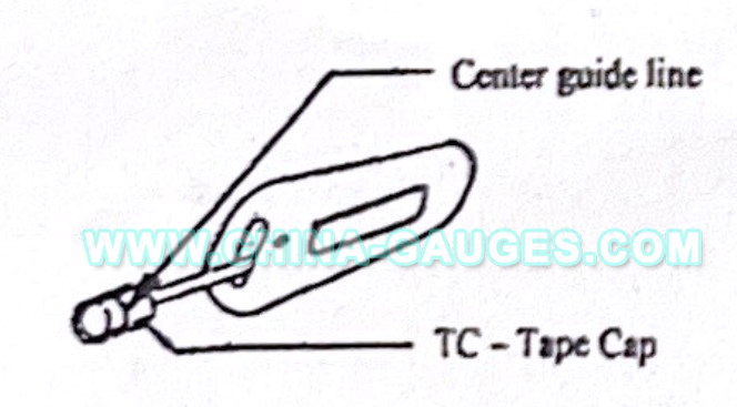
NOTE: TOOL IS INNORMALOPERATING POSITION
FIG. 1
Slide the tape cap assembly all the way onto the "pressure head" of the Tester as shown in FIG. 1, with the center guide line and the uncovered portion of the red plastic cap facing "UP." The Tester is now ready to be used.
2. APPLICATION
The tape covered pressure head is positioned on the edge to be checked for sharpness in the manner illustrated in FIG. 2. While maintaining the arm between the stops, immediately move the pressure head 2 inches along the edge as illustrated and then back to its starting position. It is then withdrawn from the edge. The total distance of engagement between the edge and the tape covered head is therefore, 4 inches.

SHARP EDGE TESTER MODEL SET-50 may be applied to edges A, B, or C
FIG. 2
3. JUDGEMENT CRITERIA
Examine the tape cap to determine whether or not penetration has occurred through the two sensing layers. If penetration has occurred, the black indicating tape will be visible through the resulting cut.
The application of the SHARP EDGE TESTER MODEL SET - 50 to an accessible edge shall not result in the cutting through of the two outer layers of the sensing tape.
NOTE: Complete details are given in the U.L. Standard 1439. The information given here is for convenience only.
*CAUTION: DO NOT OPEN TESTER, spring inside under tension could fly out and cause injury.
4. CALIBRATION OF THE TESTER
*NOTE: ALL TOOLS ARE CALIBRATED AT OUR FACTORY
*U.L. REQUIRES ALL TOOLS TO BE CALIBRATED AT LEAST ONCE A YEAR
Calibration is achieved by suspending a 1 ½ lb. dead weight (0.68 kg.) from the center of the pressure head as shown in FIG. 3.
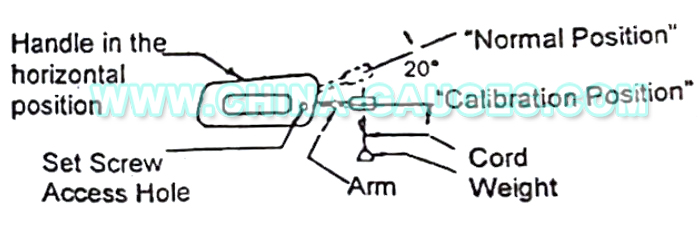
NOTE: TOOL IS IN THE UPSIDE DOWN POSITION
FIG. 3
To calibrate the Tester, position it as shown in FIG. 3 so that movement of the major axis of the arm between stops is in a vertical piane. Insert a 1/16" allen key (supplied) into the access hole and loosen the set screw, located inside the handle, approximately ¼ tum. This allows the arm to be slid in and out of the handle.
Apply the 1 ½ pound weight as shown in FIG. 3 to the center of the pressure head. Adjust the length of the arm, in or out. until the arm stavs in the "Calibration Position." Once the position is achieved, carefully tighten the set screw (Do not over tighten).
Recheck this setting by moving the arm between its stops and reapply the weight. If the arm returns to the calibration position, the setting is good.
If the arm does not return to the calibration position, readjust the arm length until it does.
Contact: Eason Wang
Phone: +86-13751010017
E-mail: sales@china-gauges.com
Add: 1F Junfeng Building, Gongle, Xixiang, Baoan District, Shenzhen, Guangdong, China
 Nina She